Wiring your custom built aircraft is not an overwhelming task. It is a part of the building process that may appear to be staggering but when analyzed it is actually fairly simple. The problem encountered by several builders is the lack of information presented in many kit assembly manuals. Usually the basics are presented in the manuals but details are often omitted due to the varying requirements of each builder. Many individuals want to have a very simple electrical system with minimum equipment while others desire sophisticated avionics, electrical gear and flaps, etc.. Because of this diversity, many kit manufacturers do not spend much time outlining the electrical system.
This article will detail the actual steps involved in installing your electrical system. Remember, all you are going to do is install the equipment you want in the desired location and then connect each component part to a power source. This narrows the installation process down to a very simple concept. You can make the wiring task as complicated as you like or you can keep it very basic and understandable.
The basic steps involved in wiring your amateur-built airplane are as follows:
- Determine what electrical equipment you are going to install
- Locate the equipment in the aircraft
- Locate the battery, bus bars, and circuit breaker/fuse panels on the airframe
- Calculate wire size and circuit breaker/fuse requirements
- Connect the electrical equipment to a power source
- Ground and bond properly
- Install proper instrumentation to monitor the system
- Complete a detailed schematic drawing of the system
Determining Equipment Requirements
You may want a very simple electrical system with only a starter and alternator. On the other hand, you may be building an aircraft that requires a somewhat sophisticated system for maximum utilization of the aircraft design. The first step is to decide what electrical equipment you want to install on your aircraft and then calculate the current draw in amps each piece will require. Your aircraft may have electrical gear and flaps. You may want strobe lights, a starter, landing lights, cooling fans, electric elevator trim, etc.. Decide now what to install then calculate the current draw of each item.
The current draw is often listed on the electrical component or it is available from the manufacturer. You will need to know the current draw in amps. This can be determined by using Ohms law or, more commonly, the wattage will be given and you can then use the power formula expressed as Power= voltage x current. Using this formula we can then find the current draw in amps by dividing the watts by the voltage. This number will be needed later to determine the size of wire needed for the piece of equipment.
You should also decide if you are going to install a 14-volt system or a 28-volt system. The majority of custom-built aircraft will use a 14-volt electrical system. Of course, you want to insure proper alternator output to power your electrical equipment. Additionally, begin to develop your schematic diagram at this point. Beginning a basic diagram at this time will make it easy to build on as you install the system.
Locate the Equipment
It is very important to plan where you will place your electrical items. If you are planning to install strobes, landing lights, navigation lights, etc. you will want to route the wiring needed for both power and ground. In many aircraft designs, this must be completed during the early phase of assembly. Otherwise, you may find that you will be unable to route electrical wire or certainly find it to be a very difficult task. After locating equipment, route the necessary wiring being sure to identify each wire. You can identify each wire by using tape that is folded over and marked. The size of wire will be discussed in a later step. Use black wire for grounding of equipment so it is easily identified. Continue your schematic as you locate equipment.
Locate the Battery, Bus Bars, and Circuit Breaker Panels
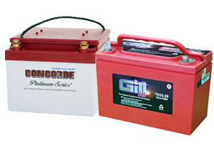
Locate the battery as close to the engine starter as possible. This is desirable due to the high electrical draw the starter requires. The battery also must be protected from high temperatures and located in an accessible area for ease of servicing. Weight and balance will also be a consideration. Often a battery will be located in the aft portion of a fuselage to balance the aircraft. Be sure to properly vent the battery.
Recalling from the previous article on electrical systemsa bus bar is a central point where wires from electrical equipment are grouped together on a piece of metal ( usually copper ) and the metal bar is then connected to a power source. You may also have a grounding bus bar to locate in your aircraft. Several builders are using a central grounding point for all equipment rather than grounding to the fuselage frame. Composite and wood aircraft often use this type of grounding. Bus bars are usually located near the instrument panel for ease of installation. You will want them to be somewhat accessible but not exposed where they could cause injury.
Circuit breaker/fuse panels are usually located in the cockpit area where they can be reached by the pilot during flight. This will normally be under an instrument panel or as a part of the instrument panel. Circuit breaker panels are also mounted on side panels. Often a bus bar will be used to connect circuit breakers together. This will allow the circuit breaker installation to serve as a bus bar. Circuit breakers can be grouped in a power bus by tapping holes in a copper strip and securing with small screws. Either terminal of the circuit breaker can be used to connect to the bus bar but you will probably find it more convenient to attach to the top terminal. The bus bar attaching the circuit breakers is then attached to a power source eliminating the need for a separate bus bar. You will probably want to fabricate more than one circuit breaker panel. These panels will then be located in different areas.
Aircraft builders often use fuse panels. A fuse bus bar is constructed using a heavy piece of copper wire and soldering the wire to the terminal of each fuse. This will also create a power bus. Most fuses require the use of soldered connections. Fuse panel installations will be cheaper than circuit breakers but you will have more difficulty changing a fuse in flight versus resetting a circuit breaker.
Calculate Wire Size and Circuit Breaker Size
Calculation of wire size will be necessary during the initial building phase. As discussed earlier, you will want to route electrical wires prior to completing the construction of the wings and fuselage. Proper wire size is critical to a safe electrical system. The match between the wire size and circuit breaker/fuse size is also critical. To determine the size of wire you will need, refer to FAA Advisory Circular 43-13. Two charts are presented; one displaying continuous flow and the other intermittent flow. What is the difference? Most aircraft electricians agree that any piece of equipment that operates more than 2-3 minutes at a time is considered continuous flow. That encompasses most items on an airframe. Intermittent flow then would obviously involve items that operate momentarily. An example of intermittent flow items is a landing gear or flaps. With that in mind, the builder enters the appropriate chart (intermittent or continuous) with the current draw of the equipment being connected to determine the proper wire size. The wire size is based upon the amount of current the wire will carry and the length of the wire.
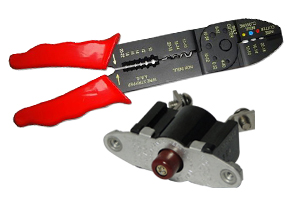
Again, we are going to use Tefzel wire that is sold under military specification MIL-W-22759/16 for unshielded wire and MIL-C-27500 for unshielded wire. Resist the temptation to go to your local electronic store and purchase wire. Most of your installation will be completed using unshielded wire. Be sure to use good quality wire cutters and strippers to cut and prepare the wire. The same applies to the crimping tool you will need. In the next article we will finish our discussion on electricity. |
